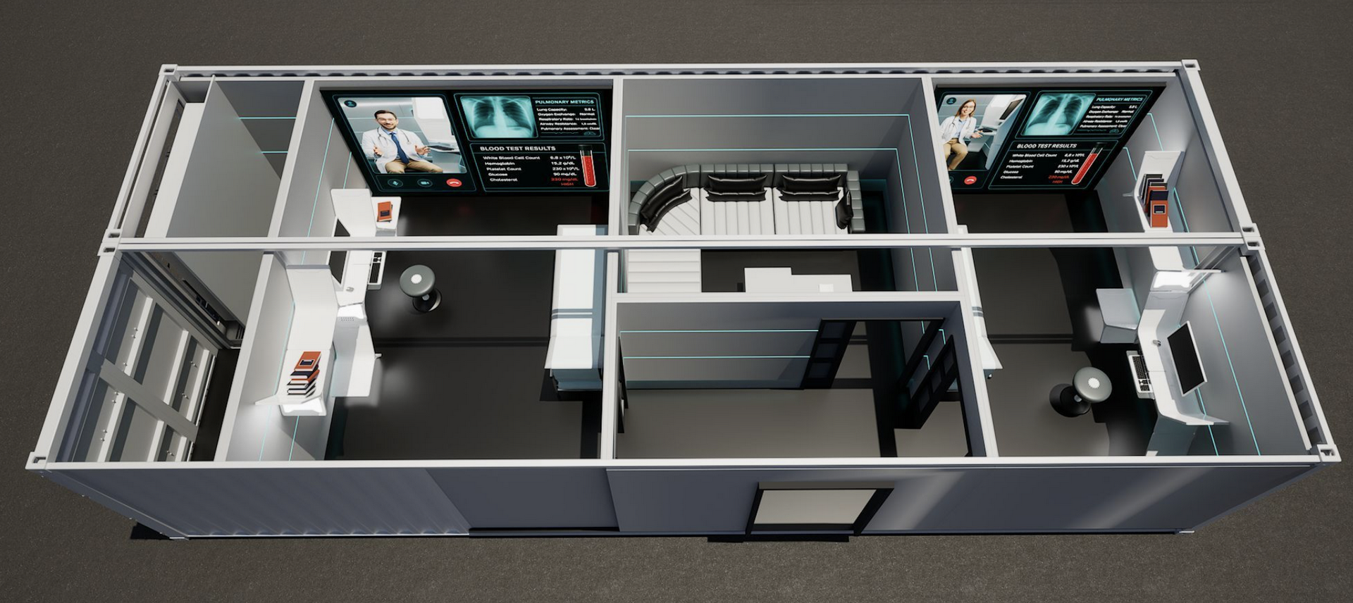
Illustrating a DX Pod
A DX Port Facility may be designed to accommodate a single container, a container pod (one or more companion containers as a "facility" illustrated above) or a container port which may be an collection of Pods.
A larger assembly of mixed use Pods and/or Ports may be referred to as a Campus, such as a ScanPort Campus which is illustrated herein and is — one of the first U.S. facilities designed to enable full body scanning in one visit, bringing together seven advanced digital scanning modalities in a single 10+/- acre campus, to build an AI enabled DigitalTwin™ of each participant.
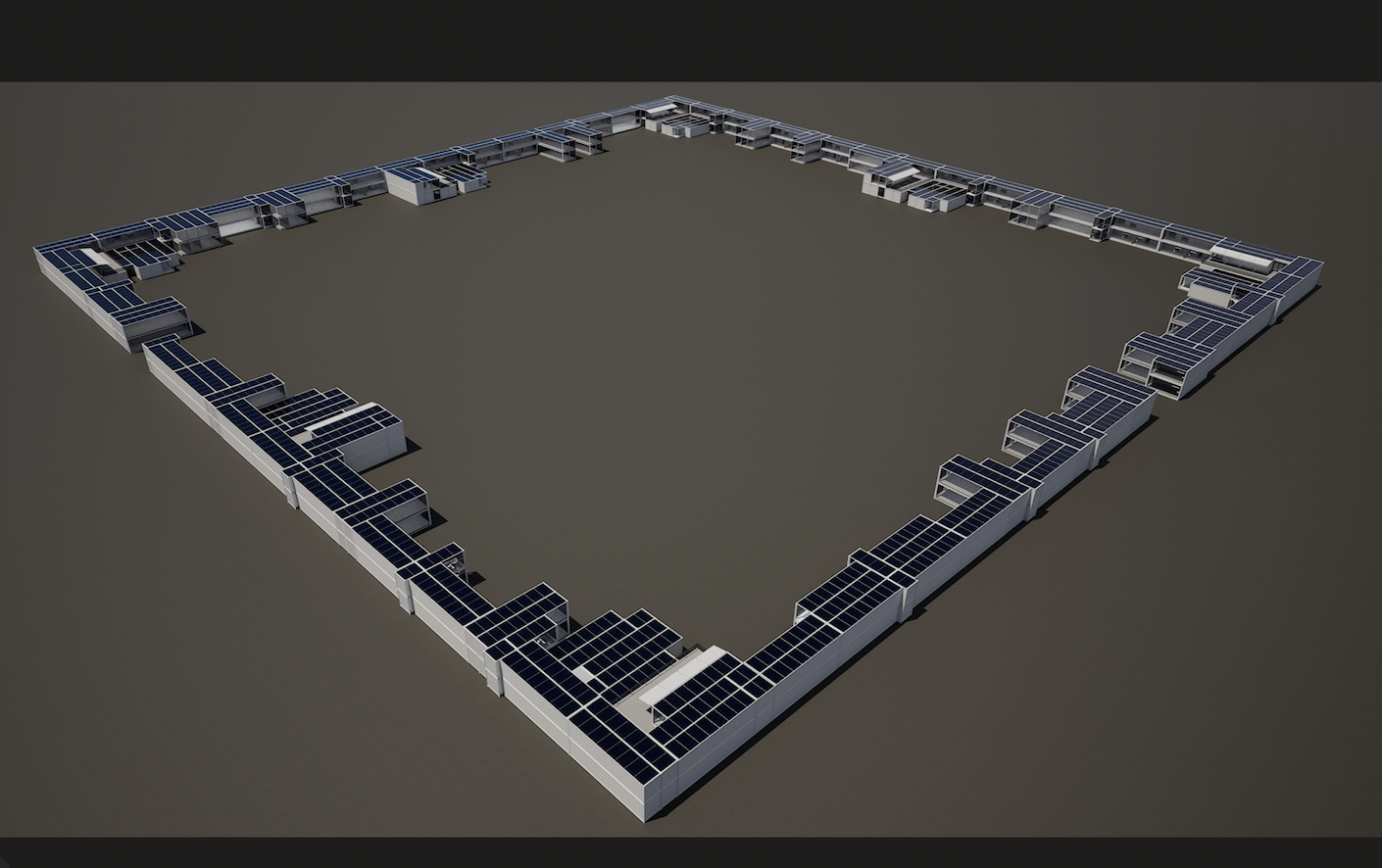
Illustrating a DX Port Campus
Each Campus is to be built around a central Thermal Utility Engine™ located beneath its Town Centre, supported by a network of geothermal wells and reinforced GreenPads that anchor each Pod™ and every future modular facility on the site. This Core distributes clean thermal energy, electrical and digital pathways, water and waste services through underground modular tunnels (GreenBox™ Thermal) that connect to all pod-based structures across the 10+/- acre Campus. These foundational elements allow the entire site — from the seven ScanPods (illustrated above) to research modules, community spaces, lodging Pods, and educational facilities — to operate on a unified clean-energy and geothermal system designed for long-term stability and expansion.
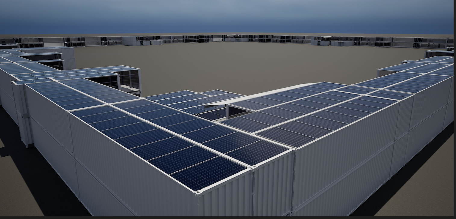
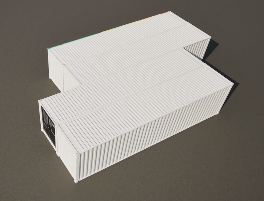
ScanPort™ Corner
At first glance, it might look like a single modular scanning facility — a compact structure built from GreenBox™ units with precision and purpose.
But a closer look reveals something more.
By extending these modules outward to include office and storage spaces, the design begins to take shape — the suggestion of a corner, the beginning of a larger form.
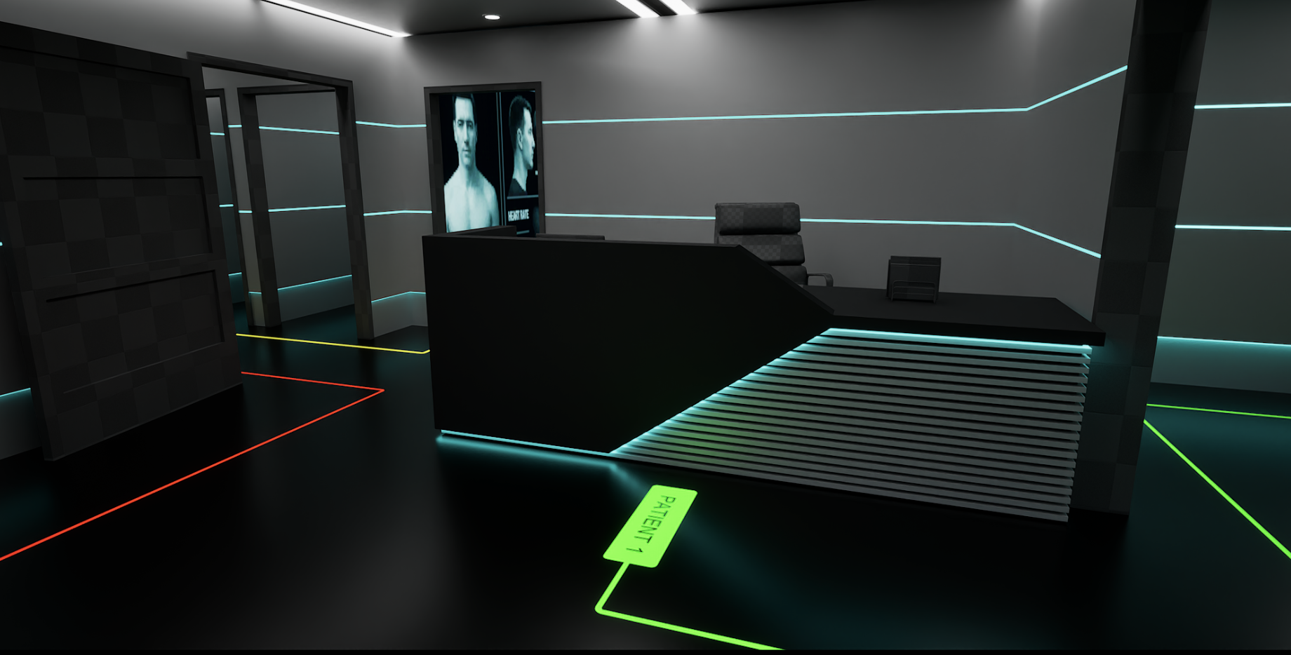
Each container serves a role: scanning, administration, data handling, or support.
Together they create a rhythm of structure that feels intentional, expandable — almost as if this corner is part of a greater whole waiting to be seen.
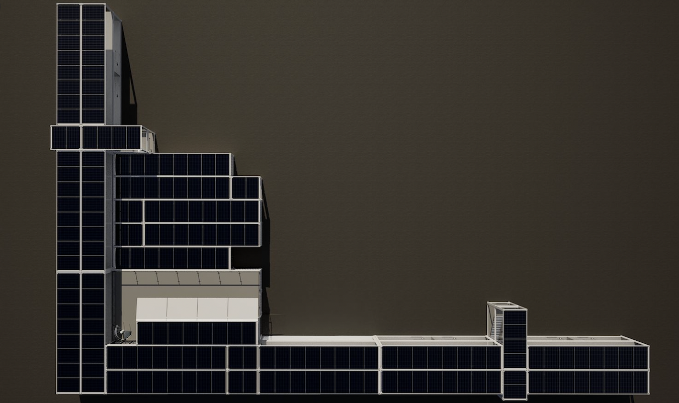
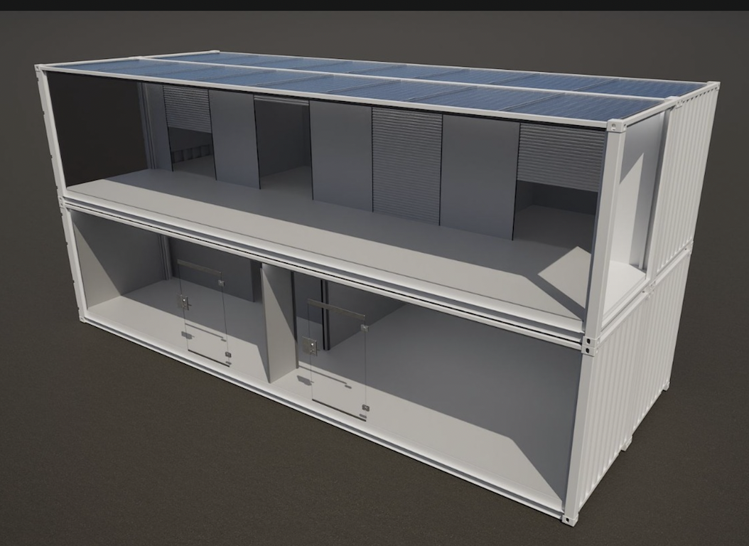
ScanPod
This view shows one of the ScanPort™ corner assemblies — a cluster of GreenBox™ modules configured around a single ScanPod™. Each corner functions as a self-contained scanning and operations unit, capable of running independently or as part of the full complex. One can start to see how extending the form with offices, storage, shops and service corridors hints at something larger — the outline of a connected system beginning to emerge.
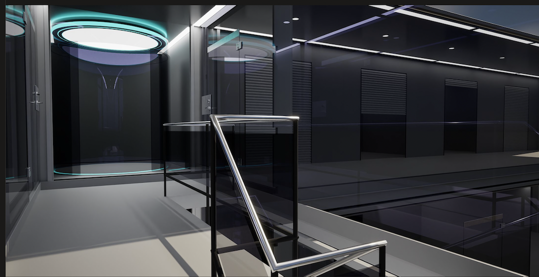
From above, the design reveals its purpose. The interior elevation shows how light, air, and power move across the top of the ScanPort™ structure. Rows of solar-integrated GreenBox™ roofs supply renewable energy to every module below, while interior walls and corridors define secure pathways for patients, staff, and data. It’s a glimpse inside a living framework — built for precision on the outside and care on the inside.
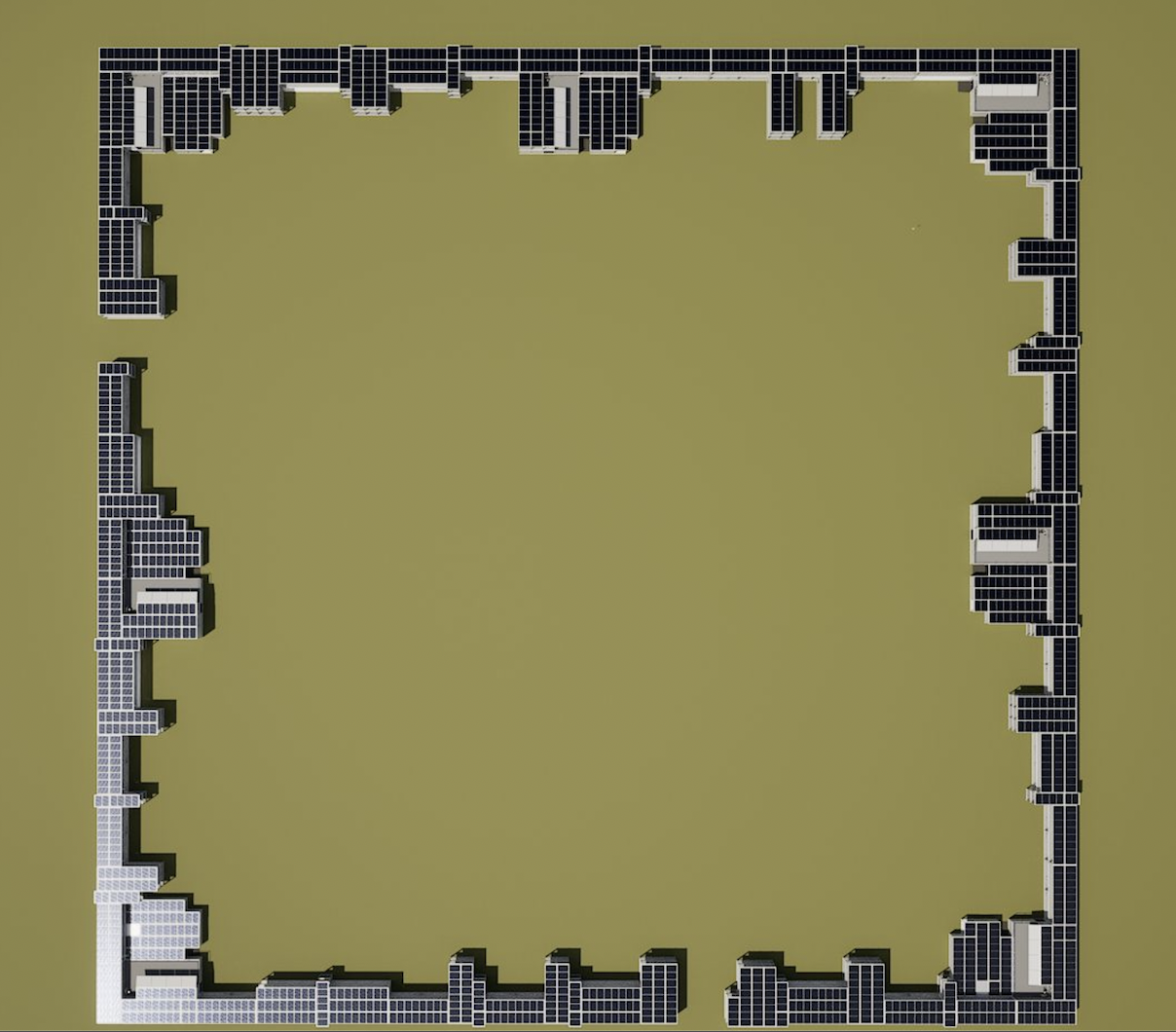
The ScanPort™ site combines precision engineering with community design.
Seven ScanPods™ define its geometry — one at each corner and three along the perimeter — with the main entrance on the fourth side.
Nineteen-foot-high exterior walls enclose the site, forming a secure compound built from ballistic- and kinetic-rated steel.
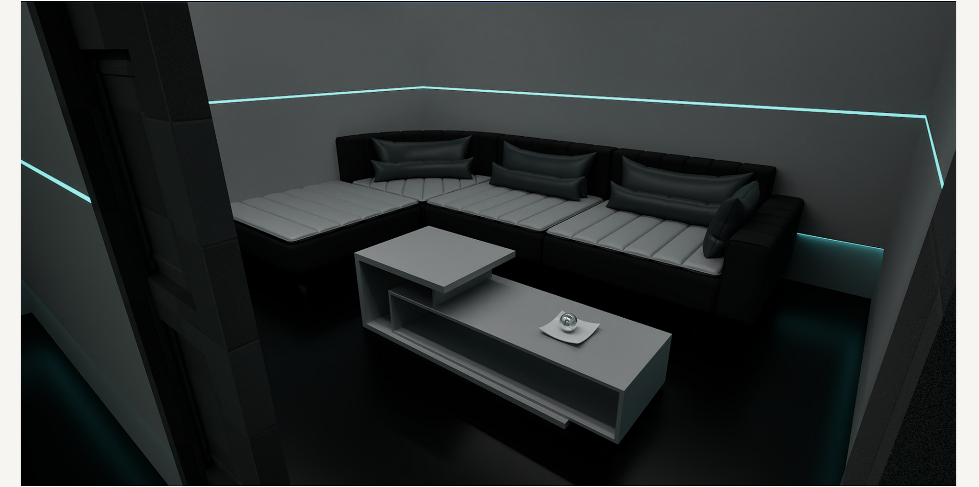
Inside, the perimeter walls do double duty, housing shops, restaurants, and offices that give the site a small-town atmosphere and everyday life.
Within the secure boundary lies a landscaped plaza with parks, fountains, solar-covered parking, and shaded walking paths.
Visitors can stay overnight, enjoy local dining, or take in community events while completing their scans in less than 24 hours.
Each ScanPort™ is designed to feel familiar, safe, and alive — a place where healthcare and daily life meet in one intelligent, connected space, a place of recovery and healing.
Each Campus is designed to take shape as an advanced form of container port, to operate under a series of de novo Government Authorities, creating a multi-use facility the core building blocks of which are ISO certified containers which generate their own electricity and are self-powered ai "edge" nodes designed to advance international trade.
These unique modules may be configured into a variety of facility shapes and sizes, supporting rapid deployment for civic, specialty, process and emergency applications.
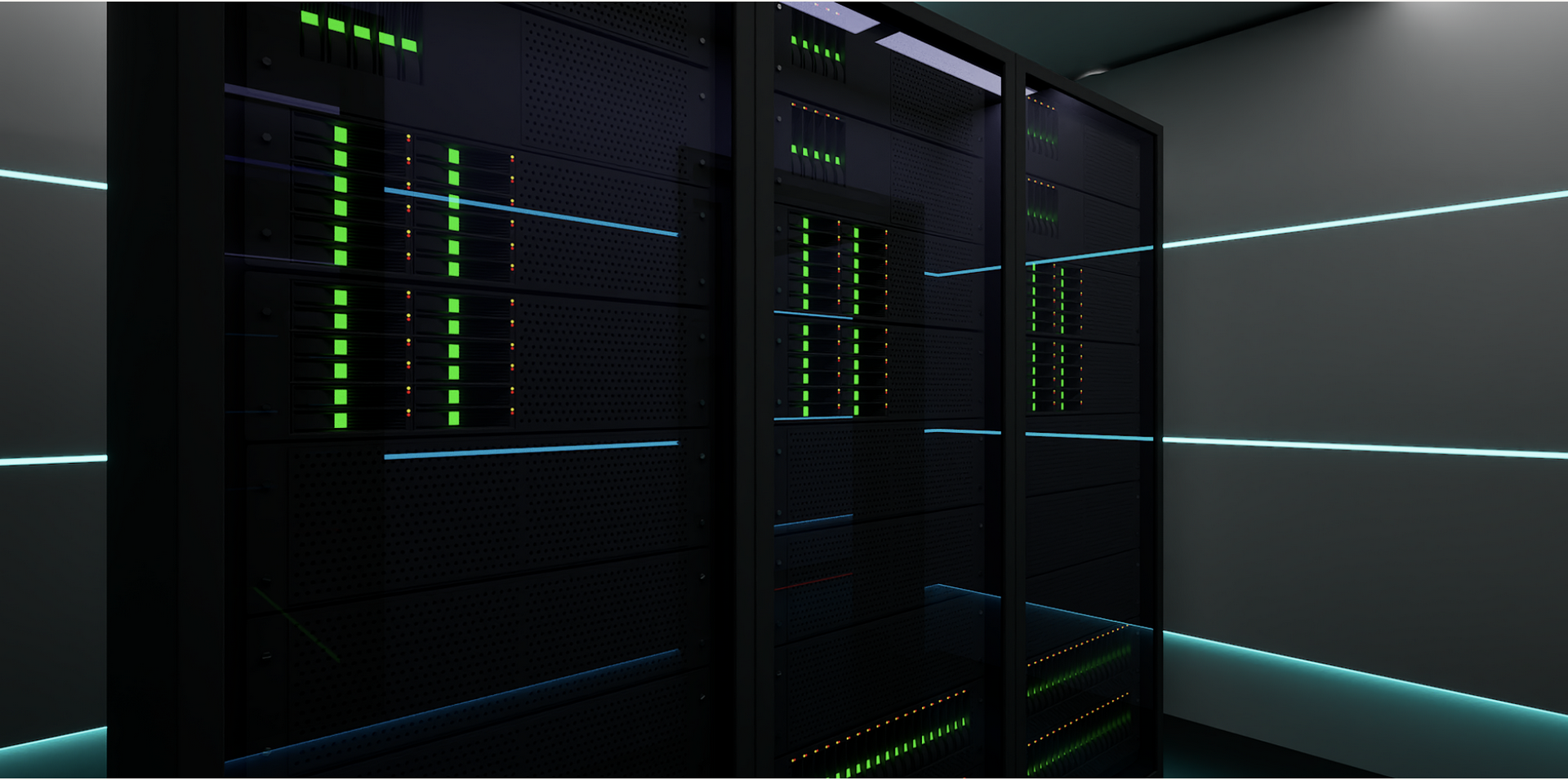
Each Campus site is designed to utilize GreenBox™ units to house each unique Pod in a collection of GreenBox™ units, each a micro power station and advanced ai compute platform.
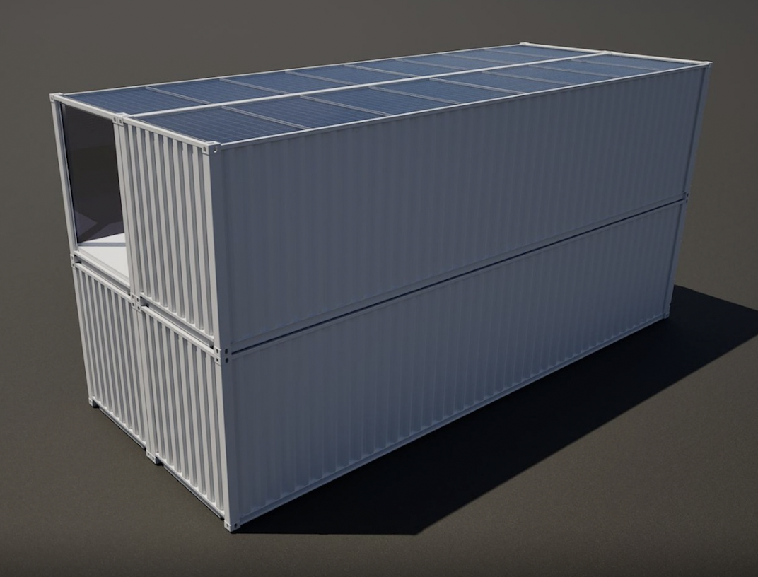
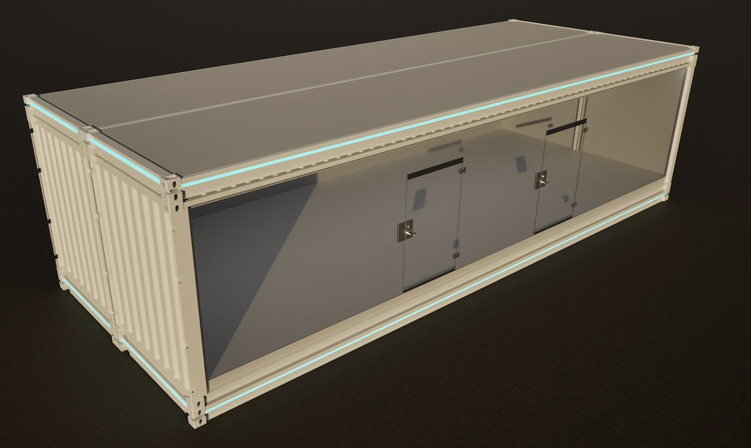
Advanced ISO certified containers designed for transit and stationary applications - generating its own electricity whle operating advanced AI "edge" nodes
Each GreenBox™ Beyond Mil-Spec™ is designed to produce its own power and operate as an advanced AI "edge" node within an international maritime decentralized mesh.
Each GreenBox ™is designed as a "transformer", a core building block for new innovation.
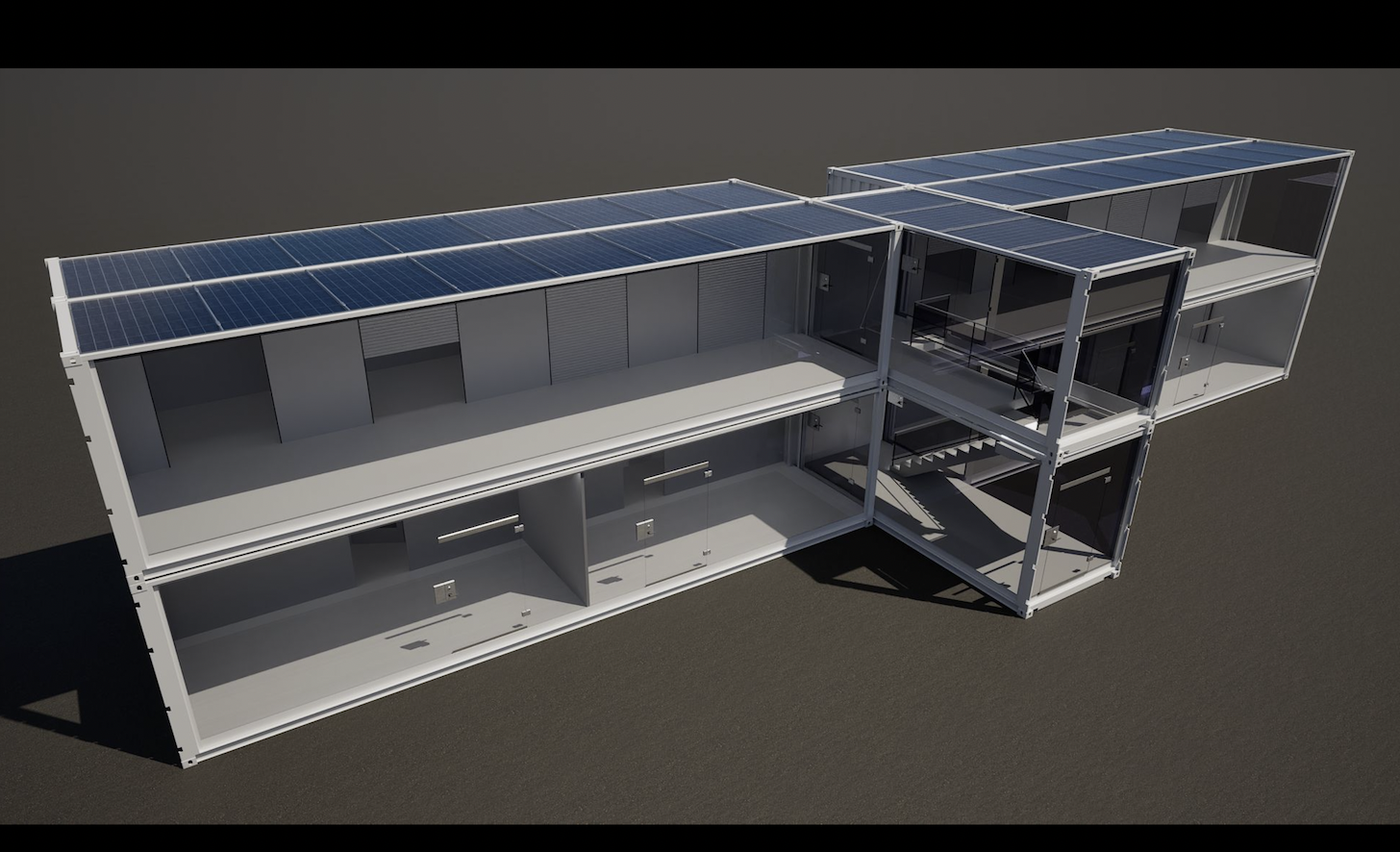
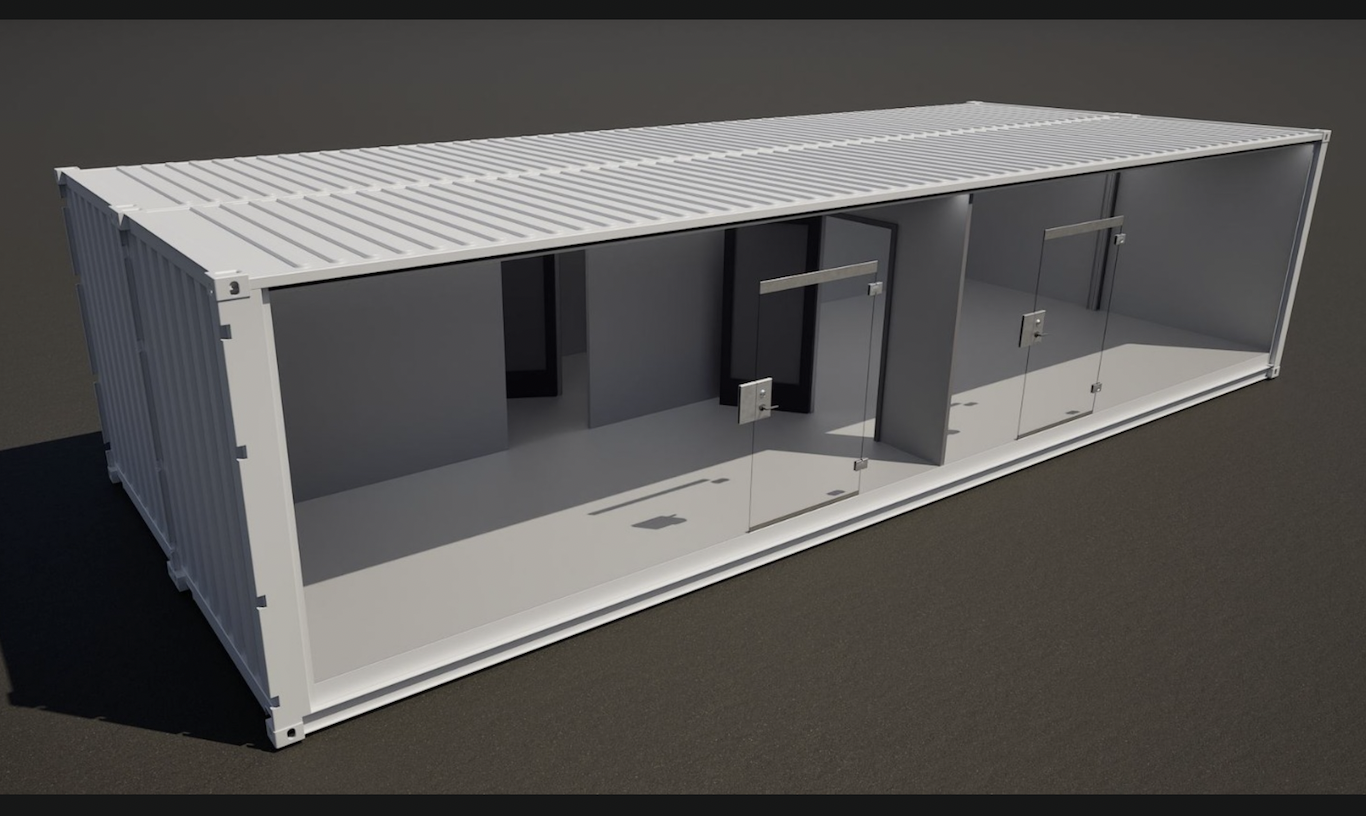
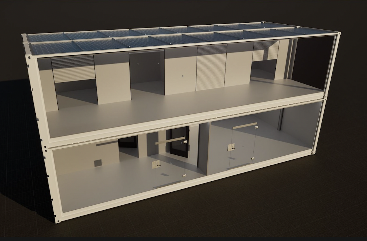
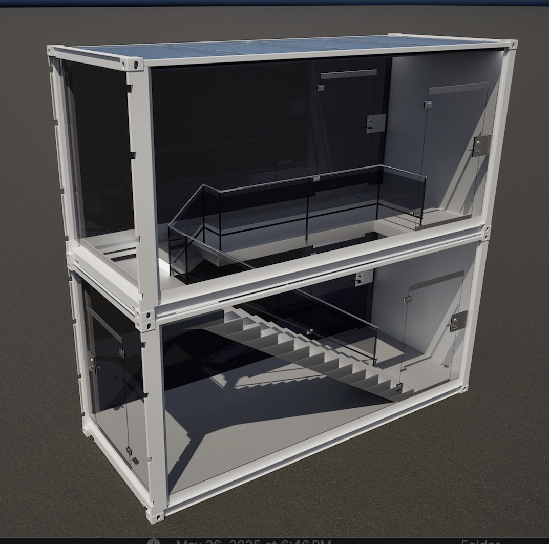
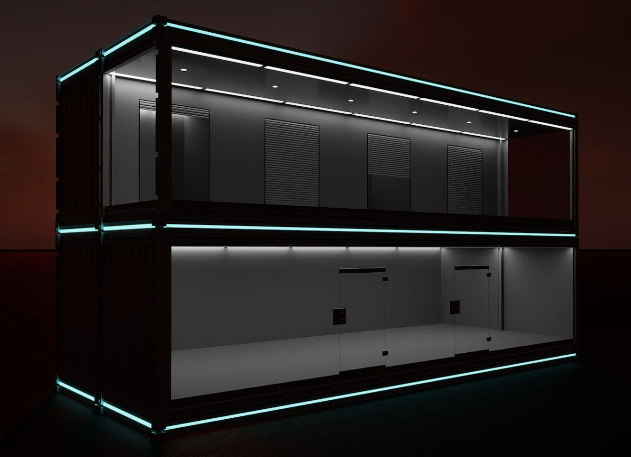
Core Module -
From these core "Pod" modules come larger, multi-use structures. Illustrated is a four-unit (2×2) configuration with integrated stairwell and elevator—built to ADA standards, which may include bullet- and blast-resistant exteriors.
These same cores can become clinics, shops, offices, restaurants, or living suites, depending on finish and fit-out.
Every unit is designed to connect laterally and vertically, giving developers near-limitless flexibility to create safe, energy-efficient environments that evolve with community needs.
The Stairwell|Elevator component provides a unique vertical exoskeleton for utilities, communications, and connectivity throughout the Campus.
The video below illustrates a ScanPod for a single digital scanning modality. This ScanPod installation includes a basement which may be used as a public storm shelter, a warehouse for emergency provisions and a bunker servicing an EMP proof data centre.
Beneath a DX Port Campus™ may exist a shared underground infrastructure environment referred to as a Thermal Utility Engine™ (“TUE”). The TUE functions as a distributed thermal, utility, communications, and operational backplane designed to support a wide variety of Pods, Ports, facilities, and modular infrastructure systems assembled throughout the Campus.
The TUE framework may include underground utility corridors, JouleBox™ tunnel systems, thermal transfer and storage infrastructure, communications pathways, vertical utility risers, maintenance access systems, and interconnected GreenPad™ infrastructure designed to support long-duration adaptive operational environments.
Above this shared infrastructure layer, a Campus may support a broad range of modular operational ecologies, including ScanPort™ facilities, research environments, public-space systems, hospitality and mixed-use Pods, logistics and utility systems, AI-enabled digital infrastructure, and other DX Port™ operational configurations.
A Campus may be assembled incrementally over time using modular Pod and Port topologies, allowing specialized operational environments to interconnect through a common utility, thermal, communications, and infrastructure framework. In certain configurations, a Town Center environment may serve as a shared public-space and operational coordination layer connecting multiple Pods, facilities, and runtime environments distributed throughout the Campus.
Each GreenBox container within a Pod is to be connected through its GreenPad to a geothermal well per Pod. Each geothermal well is designed to provide stable, renewable thermal support, while ISO-framed GreenPads distribute this energy across each GreenBox™ container footprint of a Pod™ and connect directly into underground container-based tunnel system that originates at Thermal Utility Core. The JouleBox™ tunnel system is integrated into a vertical geothermal system through the wells and horizontal geothermal system co-located with the JouleBox™ tunnels.
The system is designed to incorporate specialized solar throughs on the top level of the campus perimeter, connected into the core Thermal Utilitty Engine™ below the Town Centre.
Modular solar trough assemblies are to be mounted along the second-level perimeter of the Campus wall, integrated within the containerized utility exoskeleton. Each unit operates as a Parabolic Thermal Container, tracking solar input and concentrating heat into a high-grade thermal stream. This energy is routed through the GreenPad and JouleBox infrastructure into the central Thermal Utility Engine (TUE), where it elevates the high-temperature side of the system.
By augmenting the TUE with concentrated solar thermal input, the system enhances performance of supercritical CO₂ and Stirling engine cycles, increasing overall electrical generation efficiency while maintaining a fully containerized, modular deployment architecture.
This configuration gives every ScanPod™ — and every future pod-based facility in the campus — a consistent, repeatable foundation with long-term clean-energy support, temperature stabilization, and operational reliability.
Modern campuses rely on electricity as their primary energy currency.
The Thermal Utility Engine™ (TUE) takes a different approach.
TUE is designed around the idea that thermal energy—heat and cold—is the most abundant, flexible, and underutilized resource on a Campus. Instead of treating heat as waste and cold as an afterthought, TUE is designed to manage thermal energy as a first-class utility, alongside water, communications, and logistics.
The result is a Campus that operates more efficiently, more resiliently, and with far greater flexibility than conventional designs.
What the Thermal Utility Engine™ Is
The Thermal Utility Engine™ is the central thermal infrastructure of the Campus.
It functions as:
a BTU reservoir for storing heat and cold,
a thermal router that distributes energy where it is needed,
a temperature conditioner that sharpens hot-side and cold-side performance,
and a coordination layer that allows hundreds of independent systems to operate as a unified whole.
TUE does not replace distributed systems.
It enables them to perform better.
A Campus Utility, Not a Power Plant
TUE is not designed to generate electricity itself.
Instead, each GreenBox™ Beyond Mil-Spec™ on the Campus is an independent, self-contained unit capable of producing electricity using closed-cycle systems such as Stirling engines and supercritical CO₂ systems.
TUE’s role is to manage the thermal environment that makes those systems more efficient.
By improving temperature stability and increasing the usable difference between hot and cold, TUE allows each GreenBox™ to:
generate more electricity from the same inputs,
operate more consistently,
and remain resilient under changing environmental conditions.
In simple terms: TUE helps every unit do more with less.
How Thermal Energy Is Captured
Thermal energy enters the system from multiple sources across the Campus.
Distributed Capture in GreenBox™ Units
Every GreenBox™ naturally captures and produces heat and cold during operation. Instead of wasting this energy, TUE collects and redistributes it across the site.
Solar Thermal at the Campus Perimeter
Along the Campus perimeter, linear parabolic solar troughs are mounted above the containerized wall structure. These troughs rotate to follow the sun and concentrate solar energy into a circulating heat-transfer fluid.
Rather than producing intermittent electricity, this solar energy is delivered as usable heat into the TUE system, where it can be stored and dispatched as needed.
Environmental Exchange
The campus also uses:
natural air movement along the perimeter for cooling,
ambient heat exchange,
and subsurface thermal interaction with the ground.
Together, these sources create a diverse and resilient thermal input portfolio.
Thermal Storage and Conditioning
At the center of the campus, TUE incorporates thermal storage systems operating across multiple temperature ranges.
High-Temperature Storage
High-temperature thermal storage—such as molten-salt systems—enables heat captured during peak conditions to be stored and used later. This stabilizes operations and supports higher-efficiency energy conversion when needed.
Phase-Change Storage (PCM)
Within the underground infrastructure as well as GreenBox™ containers, phase-change materials (PCMs) are used to absorb and release heat at precise temperatures. These modules smooth thermal fluctuations and allow controlled step-up or step-down of temperature as energy moves across the campus.
Cold Storage and Heat Rejection
Cold-side stability is just as important. TUE integrates:
vertical geothermal wells for long-term thermal moderation,
horizontal geothermal loops adjacent to underground JouleBox tunnels for fast response,
and ambient and perturbation-assisted cooling using wind, pressure changes, and natural thermal gradients to enhance cooling and heat rejection—reducing mechanical load while improving system efficiency.
Perturbation-Assisted Cooling
Perturbation-assisted cooling refers to the intentional use of naturally occurring disturbances—such as wind shear, pressure changes, turbulence, and thermal gradients—to enhance heat rejection and cooling efficiency across the Campus.
Rather than relying solely on powered fans, wind mills or active mechanical systems, the Campus is designed to capture and guide environmental perturbations and convert them into useful cooling work.
At the perimeter of the Campus, wind interacting with the outer wall creates predictable upward and accelerated airflow. This airflow is shaped and channeled through perimeter-integrated infrastructure to assist with heat rejection, condenser cooling, and cold-side thermal support. Even modest variations in wind speed and direction can significantly increase effective airflow when properly guided.
Below ground, thermal perturbations caused by temperature differences between tunnels, soil, and geothermal loops are similarly leveraged to improve heat exchange. Horizontal geothermal runs adjacent to JouleBox™ tunnels and vertical geothermal wells provide additional thermal sinks that respond dynamically to load fluctuations.
By working with environmental variability instead of fighting it, perturbation-assisted cooling:
reduces parasitic electrical load,
improves cold-side stability for closed-cycle systems,
enhances overall temperature differentials, and
increases system resilience during peak heat or high-wind conditions.
In the Thermal Utility Engine™, perturbation is not treated as noise—it is treated as useful signal.
This layered approach ensures the Campus always has a reliable place to put excess heat.
The JouleBox™ Tunnel Network
Beneath the Campus surface, JouleBox™ tunnel containers form the active utility backbone of TUE.
These tunnels:
carry piping, wiring, and control systems,
house thermal modulation and PCM assemblies,
condition energy as it moves between sources, storage, and uses,
and provide protected, serviceable infrastructure that can evolve over time.
Rather than passive conduits, JouleBoxes™ are working infrastructure modules—actively shaping how energy flows across the Campus.
Why Temperature Difference Matters
Closed-cycle electrical systems do not depend on fuel.
They depend on temperature difference.
The greater the difference between hot and cold, the more efficiently energy can be converted into electricity.
TUE is designed specifically to:
raise usable hot-side temperatures using solar thermal, molten salt storage and PCM conditioning,
stabilize cold-side temperatures using geothermal and environmental exchange,
and maintain that difference over time.
This coordinated approach allows the Campus to generate electricity more efficiently and more reliably, without increasing fuel use or environmental impact.
Scalable from Pod to Campus
TUE is modular by design.
At small scale, it coordinates thermal flows across a ScanPod™ of roughly 25 containerized units.
At full campus scale, it is designed to coordinate 500 or more distributed micro-powerplants and micro-AI centers.
As the campus grows, TUE grows with it—without requiring redesign of the core system.
Beyond Net Zero
By capturing, storing, and reusing thermal energy that would otherwise be wasted, the Campus is designed to operate Beyond Net Zero.
In full operation:
on-site systems meet internal demand,
surplus clean energy can be exported to surrounding communities,
and a portion of net proceeds supports Community initiatives.
The Thermal Utility Engine™ makes this possible not by centralizing power, but by orchestrating energy intelligently across the Campus. A New Kind of Utility
The Thermal Utility Engine™ represents a shift in how Campuses are designed.
It treats thermal energy as a shared resource, not a by-product.
It favors infrastructure over speculation.
And it enables long-term resilience through modular, upgradeable design.
TUE is the utility system that makes the Campus work.
Before a single Pod™ is installed, before the gardens and cafés are built, before the Campus comes alive, the site needs a backbone. That backbone is the Thermal Utility Engine™ — a clean-energy infrastructure system that powers everything that follows.
This is not a traditional utility plant.
It is a fully integrated, containerized energy architecture built from advanced GreenBox™ units, geothermal wells, deep thermal corridors, fluid vaults, extreme temperature fluid tanks, high-pressure conduits, micro-generation modules, and intelligent thermal routing pathways. Together, they form the grid-within-a-grid that makes this DX Port™ possible.
And this is where all facility development begins.
Why this equipment comes first
Thermal Utility Engine™ is part of Phase 1 of DX Port™.
Everything else depends on it:
• The foundational Pods require it to operate.
• The perimeter wall system connects into it.
• Every future Pod plugs into it for heat extraction, cooling, micro-power, AI compute stabilization, and energy storage.
• Beyond-net-zero performance is only possible because this system exists underneath the entire campus.
Without this equipment installed, nothing above ground can function.
With it installed, the entire site can begin producing clean energy, stabilizing its thermal flows, and preparing to receive specialty Pods.
This is where private capital enters the project
The equipment that forms the Thermal Utility Engine™ ("TUE") qualifies under U.S. clean-energy (Section 48E) and digital-infrastructure rules as eligible property for accelerated incentives. For that reason, Each DX Port™ launches with an equipment purchase program ("EPP") to fund the construction, fabrication, and installation of this infrastructure, ("TUE-EPP")
TUE-EPP is the ground-floor capital that makes the remaining portion of the facility possible:
the geothermal spine, the thermal corridors, the distribution pads, the energy vaults, the micro-generation units, the specialty extreme temperature fluid tanks and the intelligent systems that allow every part of the campus to run.
High Income persons and family office participation in this program is not abstract — it places real equipment into the ground that supports build out of the core Campus and its infrastructure.
And because of how federal and state incentive structures work, participation is also eligible for something new: Self-Directed Incentive Capital™, which enables these parties to redirect tax payments into this infrastructure.
Phase Two — Expansion Within a Living Framework
Phase Two begins when the Campus has an operational heartbeat. The TUE is active, Pods are installed, the perimeter wall is partially built, and the early public-sector systems are flowing. From this point forward, the site grows inward at the same time.
The perimeter continues to rise with additional GreenBox™ containers — ultimately more than 500 of them — each of which carries its own micro-generation, thermal capture, storage, and distribution systems that plug directly into the architecture Phase One creates. They strengthen the TUE; they do not sit outside it. Every new container makes the whole Campus stronger and its energy generation larger.
Inside the perimeter, new Pods take shape. These include research facilities, educational environments, child- and family-centered community spaces, specialty modules, as well as the village-life elements that make the entire Campus human: cafés, small restaurants, offices, storage, shops, lodging, quiet spaces, energy gardens, and places to meet, talk, rest, and work. This area may include 100s of additional Pods made from more than 1000 GreenBox™ ISO containers.
If Phase One is about creating capability, Phase Two is about creating place.
It is the transition from infrastructure to community.
And because the underpinning of each DX Port is modular, adaptive, and energy-positive, Phase Two does not have a hard stop. It continues — as the site fills, as systems expand underground, as new efforts join, and as future Pods are added. Every new Pod adds electrical generation and thermal modulation capacity. Every new Pod strengthens the thermal utility engine that supports the entire Campus.
This is how a DX Port grows: by building on top of a foundation designed from the beginning to expand.
For example, ScanPort OKC begins with a foundation.
A real one — pipes, wells, vaults, thermal systems, pads — but also a foundation of sequencing.
If the order is wrong, loss of time, increased costs, frustration. If the order is right, the entire campus becomes a self-powered research and community engine.
We begin with Phase One, which is the period where the site is created in its most essential form. This is where the Thermal Utility Engine™ is built, where the underground architecture takes shape, and where the first seven ScanPods — the anchors of the entire campus — take their places along the early perimeter. Before anything else can happen, the site has to be ready to receive it.
Phase One — Building the Spine of ScanPort™
Although the public will eventually see the cafés, the gardens, the research facilities, and the extraordinary architecture of the perimeter containers, the real work of Phase One happens long before any of that appears.
It begins with identifying the land, working with the governmental authorities to establish the framework, running the engineering models, preparing the site, and placing the earliest long-lead equipment orders so fabrication can begin.
The Thermal Utility Engine™ infrastructure is the first major milestone.
It is a coordinated system — geothermal wells; large underground fluid tanks, deep thermal capture corridors; thermal distribution lines; high-pressure vaults; energy balancing pads; sensor-laden conduits; secure trenches; and the underground geometry that enables heat to move as intentionally as other sites move air or water. Much of the equipment that runs this system must be fabricated months in advance. That is why the first step of this entire project is the acquisition and fabrication of the Thermal Utility Engine™ equipment, beginning with GreenPads.
While this work proceeds with engineers, underground preparation and fabrication teams, the public-sector infrastructure progresses in parallel. The newly formed governmental authorities move forward with tax-exempt municipal bonds to fund roads, shared utilities, site access, lighting, and the other elements of the public backbone. These elements are critical, but they cannot drive the schedule — not the way the Thermal Utility Engine™ does. The TUE is the pace car for the entire development.
As the TUE infrastructure is installed and the first container connetion Pads are located and set, the seven ScanPods begin fabrication. Their delivery and placement cannot occur until Phase One TUE systems are ready to receive and interconnect with these GreenBox™ containers. Their arrival and activation mark the moment the site begins transitioning from development into operations. They are the first real Pod facilities on the ScanPort perimeter. They give the Campus its first revenue-producing capability. These seven ScanPods are expected to establish roughly 40% of the perimeter wall. They tie directly into the TUE system that has been prepared to receive them.
Phase One is expected to run through 2026 and 2027, with the objective of placing as much infrastructure “in service” as possible during early 2027 so that electrical and thermal systems can begin stabilizing, ScanPods can be installed, and the site can transition from a construction zone to a functioning organism.
ScanPort OKC is a large-scale undertaking — a campus built to last generations, a fusion of advanced digital intelligence, thermal-electric innovation, community health infrastructure, and container-based modular design. The full vision requires a carefully sequenced funding model, one that matches the architecture of the project itself: layered, resilient, and designed to expand as the campus grows.
To accomplish this, ScanPort relies on three coordinated funding pillars, each matched to a different part of the development sequence:
1. Private-Sector Funding for the Thermal Utility Engine™ (TUE) Infrastructure
The first pillar activates immediately. Before the land is fully prepared, before public-sector financing is completed, the TUE — the thermal and electrical backbone of ScanPort — must begin fabrication. This is long-lead, precision-built equipment, forming the underground and container-level architecture that allows the entire site to function.
Launching this core infrastructure begins with privately funded equipment interests. High-income participants have a unique opportunity to allocate federal, state and local tax incentives toward the acquisition of specificed TUE equipment including JouleBox™ containers to build the TUE. This early capital is not a supplement — it is the spark that enable Phase One to start. Without it, nothing at the site can be installed, powered, cooled, heated, or stabilized.
2. Site Infrastructure Funding (Private - Public)
Once a site is identified for the Campus, private sector participants acquire the land and commence initial site work and TUE instantiation. The planning and infrastructure includes roads, streets, utilities, access, lighting, and the foundational components required for Campus-wide operations. The site and site improvements are funded by the Project Developer. ''
After completion, the improved site is sold to the O|Zone Government Authority, then leased back by the Developer through a single payment lease, with renewal options. The O|Zone Government Authority may also employ tax-exempt municial revenue bonds, supported by DX Port tariff revenues. They are not funded with taxpayer dollars.
This second pillar does not drive the schedule — it runs in parallel with the private-sector catalyst that begins the project. But it is essential to delivering a fully functioning Campus. It also include integration of each of the O|Zone Government Authorities framework.
3. Private Funding for ScanPods and Modular Facilities
Once the TUE infrastructure is underway and the site begins taking shape, a separate private-sector program funds the ScanPods themselves and the specialized modular facilities that form the perimeter and interior structures. These include scanning systems, community pods, research and health pods, educational environments, and the dozens of specialized units that require custom fabrication.
This pillar runs on its own track, aligned with but distinct from the TUE. It ensures that the anchor tenants — the first seven ScanPods — and the supporting architecture can be ready for installation as soon as Phase One infrastructure is prepared to receive them.
⸻
A Funding Architecture Designed for Expansion
These three pillars create a development sequence in which:
• The TUE initiates the project and sets the pace
• Public-sector work follows in stride
• Modular facilities and ScanPods fill the campus as the backbone comes online
Together, they allow ScanPort to break ground early, accelerate the build cycle, and create a site with a long and expanding operational life.
As the Campus moves from development into operations, additional funding cycles and equipment pools may be formed to support expansion, but the initial architecture remains constant:
early private capital creates the infrastructure,
public capital is additive to the backbone, and
modular capital brings the site to life.
Pads, Pods, Campuses
The Thermal Utility Engine™ is more than supporting infrastructure beneath a Campus — it is the operational foundation that allows modular facilities, public spaces, research environments, ScanPods™, utility systems, and future Pod-based communities to function as an integrated whole.
By combining thermal orchestration, modular infrastructure, geothermal stabilization, distributed energy coordination, and adaptive GreenBox™ deployment, the TUE framework is designed to support a new generation of resilient, expandable, and human-centered operational environments. As each new Pod, Port, and Campus is added, the system is designed not simply to grow larger, but to grow stronger, more efficient, and more interconnected through time.
A New Dawn for Community Health
As the sun rises over each ScanPort™, the system quietly powers itself — solar arrays capturing light, cooling systems balancing entropy, and data syncing securely to local medical teams.
It’s not a building — it’s a living network, designed to restore health, dignity, and hope right where people live.